OpenGL Projection
We can think of the process of modeling and displaying this model on
a 2D computer screen as the same process as how we take a photograph in
the real world.
 [6]
[6]
Steps and Commands
Setting up your OpenGL to perform Projection
(these steps are in addition to your normal OpenGL
program setup)
1) Select kind of projection you wish to perform:
Orthographic and Perspective.
Design on paper the dimensions of the viewing volume and where you would
like to place the viewing volume (i.e. place the virtual camera).
-
Approach 1: This is an important step and can be done when
first creating the OpenGL program so that when you create your objects
in your 3D world you will have an idea of where they should be located
and their size in order to be visible in the 3D world.
-
Approach 2: As an alternative, you can first create
your 3D objects in your world coordinates, and then design the shape of
the viewing volume and its location
2) Create depth buffer when initialize system-
-
glutInitDisplayMode(GLUT_SINGLE|GLUT_RGB|GLUT_DEPTH);
-
above usually in main() function.
3) Next Enable depth buffer testing-
-
glEnable(GL_DEPTH_TEST);
-
above usually in a myinit() function or in main().
4)OPTIONAL - create a viewport
-
glViewport(0.0, 0.0, 500.0, 500.0);
-
usually in a myinit() function or in main()
-
default viewport is equal in dimensions to window you have created
5)Switch to GL_PROJECTION matrix mode so subsequent steps 6-7 will
affect viewing parameters:
-
glMatrixMode(GL_PROJECTION);
glLoadIdentity();
-
usually in myinit() function or in main()
6) OPTIONAL - setup viewing volume location /
direction ....same as setting up virtual camera location /direction:
-
gluLookAt(0.0,0.0,0.0, 0.0,0.0,-1.0,
0.0, 1.0,0.0);
-
usually in a myinit() function or in main()
-
default is Center of Projection of Camera (or equivalently, the Center
of Projection of Viewing Volume) is located at the origin (0,0,0) in world
coordinates and is pointed in the to look down the -Z axis and its up vector
is along the Y axis.
-
Be careful, changing this can make images in your world no longer fall
into the visible viewing volume (or frustum) and hencebe clipped and not
appear in the display window.
7) Specify Projection Type and Viewing Volume
Dimensions:
-
glOrtho(-300.0,300.0, -300.0, 300.0, 100.0,
4000.0);
-
gluPerspective(90.0, 1.0, 0.0, 1000.0);
-
glFrustum(-300.0,300.0,-300.0, 300.0, 200.0,
4000.0);
8) Inside of your drawing function(s) clear not only the color
buffer but, also the depth buffer:
-
glClear(GL_COLOR_BUFFER_BIT | GL_DEPTH_BUFFER_BIT);
|
Viewport
-
Controls the area that is visible to the computer/camera, often called
the clipping window. If these viewing parameters are not set
correctly, the object can be distorted or not appear in the final rendered
view in the window.
-
See Figures 2.35/2.36 of BOOK!!!
-
Default veiwport is the entire OpenGL window that you have defined (see
glutinitWindowSize()) .
-
glViewport() specifies the
viewport.
void glViewport( GLint x,
GLint y,
GLsizei width,
GLsizei height )
-
x, y Specify the lower left corner of the viewport rectangle, in
pixels. The default is (0,0).
-
width, height Specify the width and height, respectively,
of the viewport. When a GL context is first attached to a window,
width and height are set to the dimensions of that window.
For example:
glViewport( 0,0,300,300 );
|
LookAt: The Camera Position- Position of
Viewing Volume
You can set the location of the camera (equivalently the location of
the viewing volume) by
a call to : gluLookAt()
-
This is optional
-
Default: Center of projection (location of camera/eye)
is at world coordinates origin (0,0,0). The camera is point (its
optical axis) down the -z axis. Finially, its up vector is
along the Y axis.

void gluLookAt( GLdouble EYEx, GLdouble EYEy, GLdouble
EYEz,
GLdouble ATx, GLdouble ATy, GLdouble ATz,
GLdouble UPx, GLdouble UPy, GLdouble UPz);
-
EYEx,EYEy,EYEz Specify location of the C.O.P, the location of camera/eye.
-
ATx,ATy,ATz Specify point looking at.
-
UPx,UPy,UPz Specify direction of up vector.
For example:
gluLookAtt( 0.0,0.0,10.0, 0.0,0.0,0.0,
0.0,1.0,0.0);
thus optical axis (camera looking direction) = -z axis.
COP at (0.0,0.0,10.0). And up direction is y axis.
|
Viewing, modeling and projection are addressed
with matrices.
-
GL_MODELVIEW matrix is used to specify viewing and modeling
parameters.
-
GL_PROJECTION matrix is used to specify projection parameters,
e.g. perspective.
In order to declare a projection type we just switch the matrix mode to
GL_PROJECTION as shown in the code below. In the code
below, the first call - to glMatrixMode(<matrix>)
defines which matrix to work with.
Perspective Projection via glPerspective()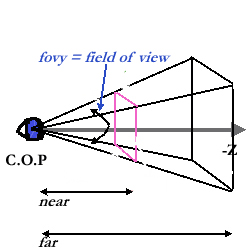
Perspective projection mimics roughly how the human eye projects 3D
objects into its retina, and also mimic how a camera projects 3D objects
to pixels in its 2D image plane.
We must define a perspective projection matrix. A simple way to do this
is by using the GLU library routine gluPerspective. There
are many other ways to define and manipulate the projection matrix, but
we will always use this simple method and maintain its parameters for an
entire application.
PERSPECTIVE PROJECTION DECLARATION
glMatrixMode( GL_PROJECTION );
gluPerspective( 90.0,1.0,1.0,10.0 );
glMatrixMode(GL_MODELVIEW); //goto modeling
where
void gluPerspective( GLdouble fovy,
GLdouble aspect,
GLdouble zNear,
GLdouble zFar )
-
fovy Specifies the field of view angle, in degrees,
in the y direction.
-
aspect Specifies the aspect ratio that determines the field
of view in he x direction. The aspect ratio is the ratio of
x (width) to y (height).
-
zNear Specifies the distance from the viewer to the
near clipping plane (always positive).
-
zFar Specifies the distance from the viewer to
the far clipping plane (always positive)
|
The following picture demostrates these arguments used in perspective projection:
 [6]
[6]
Example Perspective Projection on a Wireframe Model (from: http://www.dcs.ed.ac.uk/teaching/cs4/graphics/Web/lectures)

What happens when you change the Field of View:
| FIELD OF VIEW = 45 degrees |
FIELD OF VIEW = 90 degrees (wider angle) |
 |
 |
Perspective Projection via Frustum Specification,
glFrustrum()
| PERSPECTIVE PROJECTION DECLARATION
glMatrixMode( GL_PROJECTION );
gluFrustrum( -500.0,500.0, -500.0, 500.0,
100.0, 1000.0);
glMatrixMode(GL_MODELVIEW); //goto modeling
where
void gluPerspective( GLdouble left,GLdouble
right,
GLdouble top, GLdouble botton,
GLdouble zNear,
GLdouble zFar )
-
left Specifies far left point in frustrum
-
right Specifies far right point in frustrum
-
top Specifies top point in frustrum
-
bottom Specifies bottom point in frustrum
-
zNear Specifies the distance from the viewer to the
near clipping plane (always positive).
-
zFar Specifies the distance from the viewer to
the far clipping plane (always positive)
|
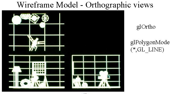
Orthographic
Othrographic see Figure 2.33, 2.34 , p.g.62 of BOOK
| ORTHOGRAPHIC PROJECTION DECLARATION
glMatrixMode( GL_PROJECTION );
gluOrtho( 0.0, 100.0, 0.0, 100.0, -2.0,
100.0 );
where
void gluOrtho( GLdouble left,
GLdouble right,
GLdouble bottom,
GLdouble top,
GLdouble near,
GLdouble far )
-
left Specifies the far left (-x) edge of viewing
volume
-
right Specifies the far right (+x) edge of viewing volume
-
bottom Specifies the bottom (-y) edge of viewing
volume
-
top Specifies the top (+y) edge of viewing volume
-
near Specifies the closest (-z) edge of viewing
volume
-
far Specifies the farest (+z) edge of viewing volume
void gluOrtho2D( GLdouble left,
GLdouble right,
GLdouble bottom,
GLdouble top,
-
same as above with near=-1, far=1
|
Example Orthographic Projections on a Wireframe Model (from: http://www.dcs.ed.ac.uk/teaching/cs4/graphics/Web/lectures)