Chapter 2: Basics


2. Basics

Mouse Usage
Anim8or requires the use of a mouse with two buttons.  You use the left one most of the time to select, move, and change objects.  When you are selecting things, the left button always deselects everything beforehand, so that only a single item remains selected.  The right button, on the other hand, allows you to select multiple items by adding newly selected items to those already so.
When moving, rotating, or non uniformly scaling something, the left button changes the X and Y axii.  Moving to the left or right affect the X axis, and up and down the Y.  The right button changes the Z axis.
You can often double click on something to bring up an edit dialog for that item.
Where's Undo?
As of version 0.5, Anim8or has a fairly complete undo command for the Object amd Figure Editors.  As long as you stay in either Editor you can undo and redo multiple editing commands.  A history is kept of as many changes as can fit in the undo buffer, about 1 MB of memory.  So unless you're editing large models, you will be able to undo more than one operation
You use the Edit->Undo and Edit->Redo menu commands to apply undo's and redo's.  Or you can use the keyboard shortcuts of Ctrl-Z and Ctrl-Y.
For the Sequence and Scene Editors, however, Undo is not yet implemented.  So, you can still use the original (rather simplistic, and to some people annoying) substitute.  When you are dragging a mouse in the main window to change something, say an object's orientation, and you think "Oops! I didn't want to do that!", just keep on dragging the mouse until it's outside the active view window and release the button.  This will cancel the operation.
So, when using the other Editors, I still offer the same advice: "Save Early, Save Often!".
Toolbars and Menus
Here is a portion of a typical toolbar.  It has several sections in it that control different aspects of its behavior.  The first thing that you will notice is that markings on some of the the buttons are in WHITE , some are in BLACK, and a few are in GRAY .  The white ones indicate that the associated mode or option is currently selected or in effect.  The black ones indicate a state that is not selected.  The gray buttons show options that are not currently available.

The top group of buttons on each toolbar act as a radio set indicating the current editing mode of the active view.  When you click on any one of them,  it becomes hilighted and that mode is selected.  All of the others are deselected.  The meanings of the various buttons in this group, and the other common buttons, are described below.

Common Button Meanings
The topmost group can have up to 4 buttons in it.  When you click on one it set the indicated mode, and changes the lower part of the toolbar to show the functions that are present in your new mode.  The different modes are:
This button indicates that you are in the most basic select-and-edit mode for the editor that you are currently using.  You will use it for most operations, such as selecting things and common editing actions.
This button is used for changing your view or views of your workspace.  With it you can pan, zoom, tilt, and scale each view independently.
In this mode you can move and rotate the pivot for objects in your workspace.  A pivot is the point and orientation that are used when you scale and rotate each object.
You use this button to move into point edit mode.  It allows you to add, move, and modify individual points, edges, and faces on editable mesh objects.
The next row of three small buttons  show the three axis of the 3D world.  They indicate which axii are "unlocked', allowing you to move and rotate things in each direction.  You can individually select or deselect them, and thus restrict the movement of objects that your are changing.
Below these buttons you will find three more small buttons  that form a radio group.  They show the current coordinate system your are using.  You can use either world, object, or screen coordinates when you manipulate things.
You will find that there are several common toolbar buttons that have the same or similar meanings in more than one editing mode.  They are described next.
You use the arrow button to select individual components.  When you click on an object using the left mouse button, you select it and deselect any previously selected objects.  When you use the right mouse button, you leave any currently selected objects selected, and select additional ones.
With this button you can click and drag to show the corners of a selection rectangle.  Any and all objects that fall within that area are then selected.  Again, the left mouse deselects any previously selection items, while the right mouse does not.
This is the move function.  You set it when you want to move your objects around on the screen.  When you press the left mouse button within a view window you can drag anything that is currently selected in the X and Y directions by moving the mouse to the left and right, or up and down.  The objects will move along with your mouse.  Similarly, the right mouse button will move them along the Z axis which is usually into the screen.
This is the rotate button, used for rotating things.  When you click and drag the left mouse button, any selected objects will rotate around the X and Y axii along with your mouse.  You can use the right button to rotate them around the Z axis.
This is the non-uniform scaling button.  With it you can scale most objects independently in the X any Y directions using the left mouse button, and in the Z direction with the right mouse button.
This scales objects in all dimensions simultaneously.
There is also a VCR style set of buttons  for controlling the playback of your animations.  You use its buttons in the same manner as those on a standard VCR or tape player.
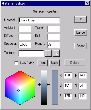
Keyboard Shortcuts
You can use keyboard shortcuts for several common operations.  Some are shortcuts for menu commands, and they are shown to the right of the command name in the menu. 
Ctrl-A Select All - Select all objects in the current view.
Ctrl-C Copy - Copy any selected objects onto the Anim8or clipboard.
Ctrl-F Filled view - Show objects as solid instead of as a "wireframe: made out of lines.
Ctrl-V Paste - Paste applicable Anim8or objects from the clipboard into the current object.
Ctrl-W Wireframe view - Show objects as lines instead of solids.
Ctrl-X Cut - Cut any selected objects from the current workspace, and copy them into the Anim8or clipboard.
Ctrl-Y Redo - Reapply an Undo command.
Ctrl-Z Undo - Undo the last editing command.
Ctrl-Shift Temporarily change into select mode.  This allows you to quickly select a new object by pressing the Control and Shift keys simultaneously and clicking on the object, and return to your previous mode when you release the keys.
Arrow
Keys
You can use the arrow keys to move, rotate, and scale objects by small amounts in the Object editor.
Anim8or Object Libraries
You can use any Anim8or .an8 project file as a library.  Objects, Figures, Sequences, and Scenes can all be imported to another Anim8or project with the Object->Import, Figure->Import, etc. menu commands.  You can also export individual Objects and such with similar Object->Export commands.
Grid Control
You can set the size of the background grid used in the editing views, or you can let Anim8or pick a default size that changes with how much you zoom the view so that it always shows a reasonable number of grid lines.  Use the Options->Grid command to show the grid dialog:

There are two grid sizes that you can set.  One is used in the Object, Figure, and Sequence Editors, and the other is used in the Scene Editor.

You can also set snap-to-grid for the Object editor by checking the Enable box in the Snap to Grid section.  This will position objects you move at locations on a grid, making it easy to align them.  Snap-to-grid also controls the size and rotation for many operations to give you more control on other aspects of modeling.  You set the size of the grid snap in the Spacing entry.
Material Editor
The material editor is used whenever you need to design the color, texture, transparency, and other visual properties of an objects appearance.  An example is shown below.
Most of the entries should be fairly obvious to most of you, but a couple of them can probably use a bit of explanation, so there's a short description of them in the following table:
Material The name of the material.  This field can be left as the default "material00", but it is a good idea to give each material a useful name.
Ambient The value of the ambient component.  The ambient, diffuse, and specular values range from 0.0 to 1.0.  If left blank, their values are taken form the global default material's values.
Diffuse The value of the diffuse compnent.
Specular The value of the specular component.
Trans* The transparency of the material.  Actually, it's the opaqueness of the material.  1.0 is fully visible, while 0.0 is completely transparent.
Brill* The "brillience" factor.  This setting changes the appearence of the diffuse component.  Normal objects have a value of 1.0.  If you increase it by a small amount to 1.5 or 2.0, the material takes on a sort of matellic sheen, or for brighter colors, a deeper, richer appearence.
Rough The roughness of the material.  A higher value makes the surface look shinier.  It it tempered by the value of the Specular component.  Values range from 1.0 (not at all shiny) to 100.
Texture This is the name of the current texture that is used with this material.  Textures change only the diffuse color.
"..." Press this button to load and view texture maps with the texture properties dialog.
uv Not currently enabled.
Two Sided You can select this item, to give the material a different material for it front and back sized.  The front and back buttons will show which side's properties are currently showing.
Delete This button deletes a material.  You will be notified if it is currently in use and given a chance to cancel the delete.
*Note: this variable only affects rendered images.  It is not visible in interactive sessions.
Texture Editor
The texture editor allows you to load, view, and manage the textures that you use in your animations.  An example is shown below:
Visual Quality
You can control the quality of the images shown when you edit, as well as the quality of the images output to files.  These are controlled through the Viewport Parameters dialog that is found under the View->Preferrences menu.  It looks like:
The last area, Frame Rate, sets the number images used to make one second of animation.  All .avi file output is generated with this frame rate.  If you check the Limit Playback box, then Anim8or will limit the rate it plays animations in the Sequence and Scene Editors.  Otherwise they will be played at the fastest possible speed.
OpenGL Workspace
This section controls the appearance of your interactive workspace.  You can view your objects as wireframe models, as flat faceted solid objects, or as smooth shaded solid objects.
Most graphics cards display smooth shaded images at the same speed as flat shaded ones, so you might think that flat shading wouldn't be very useful.  But it is sometimes helpful to see individual facets on a model.
Texturing, and mipmaps, can sometimes slow the response of your computer, so use the check boxes to enable or disable them as you see fit.  Also, texturing can hide the structure of your models, so you don't always want to see it.
File Output
This section controls the appearance of your interactive workspace.  File images are rendered using a software renderer instead of an OpenGL accelerator, so the speed of your file renderings can be effected quite severely by the settings that you choose.
Gouraud shading is faster that Phong, but isn't nearly as good at showing highlights.  Similarly, anti-aliasing helps to remove jaggies but takes several times longer to do.
Frame Rate
The last area sets the Frame Rate, or the number of images used to make one second of animation.  All .avi files you make will have this frame rate.  If you check the Limit Playback box, then Anim8or will also limit the rate it plays animations in the Sequence and Scene Editors.  Otherwise they will be played at the fastest possible speed.
Saving Images as .jpg and .bmp Files
You can make a quick preview image of any view that you are working on with the File->RenderPreview command.  You can also save this image to a .jpg or .bmp file, or print it, from within this command.
Printing
Anim8or has the usual Print and Print Preview options in the File menu.  But it offers one additional level of control of your printed images, by letting you control the size and other properties of the bitmap image used in printing.  It is not at all uncommon for a color printer to have a resolution of 1440 by 720 dpi.  But generating an 8.5" by 11" image at this resolution is not practical!  Instead Anim8or uses a default size of 1024x768 which you can adjust to suit your needs.

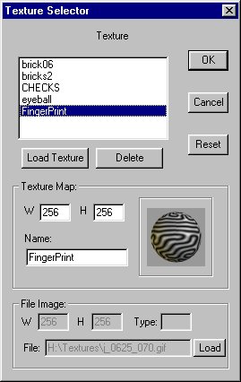
This page was last updated on May 4, 2000.