Vision Tracking
Keywords:
InstantVision,
devices,
vision
Author(s): Mario Becker
Date: 2008-06-10
Summary: This tutorial shows you how to do vision based tracking. As an example we will create a marker tracker.
Introduction
This examples shows some internals of InstantVision (short: IV). For information about integrating tracking in InstantPlayer refere to MarkerTracker tutorial.Tracking in General
The Tracking module is based on a secondary library, which is why the configuration of a tracking system is somewhat out of the X3D or VRML style and is located in an additional xml file which must be referenced from your scene definition. The tracking configuration can be done by editing the xml file or with the InstantVision GUI which is described in the linked tutorial. Here we focus in the xml describtion and some internals.
Some terms used in this tutorial...- World :
- The desciption of the world how the tracking system sees it. It contains one ore more TrackedObjects.
- TrackedObject :
- Describes the objects to be tracked, thus this node contains all information about an object which should be tracked
- Marker :
- One way to track things is the use of a marker. To describe a TrackedObject with a marker this node is added to the TrackedObject
- Camera :
- A camera is used in every vision tracking system. The node contains one Intrinsic and one Extrinsic data node.
- ExtrinsicData :
- Part of the camera description, contains the parameters descibing the position and orientation of the camera in the world.
- IntrinsicData :
- Second part of the camera description, describes the internal parameters of a camera like resolution, focal length or distortion.
- ActionPipe :
- The execution units (Actions) in InstantVision are arranged in an execution pipe which is called an ActionPipe.
- DataSet :
- All data used in InstantVision are placed in the DataSet and have a key(name) to refere to them.
The Example
The examples below can be testet by opening the in InstantVision. Here we construct a simple marker tracker step by step.
First an "empty" IV config, it contains a section ActionPipe and a DataSet.
Code: The visionlib.pm file
<?xml version="1.0" encoding="UTF-8" standalone="no" ?>
<VisionLib2 Version="2.0">

  <ActionPipe category="Action" name="AbstractApplication-AP">
  </ActionPipe>

  <DataSet key="">
  </DataSet>

</VisionLib2>
VideoSource
To get some live to it we add a VideoSourceAction. This will read in an image from a connected camera.
Code: The visionlib.pm file
<?xml version="1.0" encoding="UTF-8" standalone="no" ?>
<VisionLib2 Version="2.0">

  <ActionPipe category="Action" name="AbstractApplication-AP">

    <VideoSourceAction category="Action" name="VideoSourceAction">
      <Keys size="2">
        <key val="VideoSourceImage"/>
        <key val=""/>
      </Keys>
      <ActionConfig source_url="ds"/>
    </VideoSourceAction>

  </ActionPipe>

  <DataSet key="">
  </DataSet>

</VisionLib2>
The example above uses DirectShow (or QT on the Mac) to access a camera. This should work for all cameras which support it, these will usually have a WDM driver to be installed. To use other cameras you need to change the VideoSourceAction/ActionConfig:source_url field. There are also a number of arguments which can be passed to the video source driver. The arguments are added to the source url like this: driver://parameter1=value;parameter2=value.
Some drivers and their parameters are (available on platform in parentheses):
- ds :
- (win32, darwin) Windows driver as mentioned above, on a Mac this is the same as "qtvd" Parameters are: device - string name of the camera, mode - string name of the mode, framerate - integer. The driver compares the given parameters to whatever DS reports about the camera, if there is a mach, the parameters are used, other values are ignored.
- vfw :
- (win32) Old VideoForWindows driver. That is a good luck driver, no parameters implemented.
- v4l2 :
- (linux) Works with video4linux2. Parameters are device = string with string beeing a path to the device like "/dev/video0", width=x and height=y are also understood and the next best videoimage size supported by the driver is selected
- ieee1394 :
- (win32) FireWire DC cameras which run with the CMU driver http://www.cs.cmu.edu/~iwan/1394/index.html on windows. No parameters available for now.
- ieee1394 :
- (linux) FireWire DC cameras which run with the video1394 kernel module and libdc1394 (coriander), which includes PGR devices. Parameters are: unit - integer value for selecting a camera at the bus, trigger - boolean [0,1] 1 switches on external trigger, downsample - boolean [0,1] downsamples a bayer coded image to half size, device - string like "/dev/video1394/0" the device file to use.
- ieee1394pgr :
- (win32) PointGreyResearch cameras, license needed Parameters are: unit - integer value for selecting a camera at the bus, trigger - boolean [0,1] 1 switches on external trigger, downsample - boolean [0,1] downsamples a bayer coded image to half size, mode - string value to select a mode, when passing "mode=320" some mode with a resolution of 320x240 is selected.
- ueye :
- (win32, linux) IDS imaging uEye cameras, license needed (more adjustments then the ds drivers) Parameters: downsample - boolean [0,1] downsamples a bayer coded image to half size,
- vrmc :
- (win32) VRmagic cameras, license needed, No parameters supported yet.
- qtvd :
- (darwin) MacOSX QuickTimeVideoDigitizer, parameter unit=int selects a capture device if there is more then one.
Some of these drivers require additional libs/dlls which must be installed on your system and in the path.
MarkerTracker
Now we add a ImageConvertActionT__ImageT__RGB_FrameImageT__GREY_Frame :-) this simply converts the RGB Image from the VideoSourceAction, named "VideoSourceImage", into a greyscale image as it is needed by the MarkerTrackerAction. The grey image is stored as "ConvertedImage".
We also add the MarkerTrackerAction itself. Its first 3 keys are interesting, the first is the image from which the markers should be extracted, the second is an named "IntrinsicData" which we add later to the DataSet, it is a camera description. The third key points to a World object which defines the markers to be tracked.
Finally there is a TrackedObject2CameraAction. This is not realy needed here but later when you want to transfer the tracking results to InstantPlayer it creates Camera object which is needed by the interface between InstantVision and InstantPlayer. A Camera object encapsulates IntrinsicData and ExtrinsicData - both describe the camera parameters and thus the tracking result.
Code: The visionlib.pm file
<?xml version="1.0" encoding="UTF-8" standalone="no" ?>
<VisionLib2 Version="2.0">

  <ActionPipe category="Action" name="AbstractApplication-AP">
    <ImageConvertActionT__ImageT__RGB_FrameImageT__GREY_Frame category="Action" name="ImageConvertActionT">
      <Keys size="2">
        <key val="VideoSourceImage"/>
        <key val="ConvertedImage"/>
      </Keys>
    </ImageConvertActionT__ImageT__RGB_FrameImageT__GREY_Frame>
    <MarkerTrackerAction category="Action">
      <Keys size="5">
        <key val="ConvertedImage"/>
        <key val="IntrinsicData"/>
        <key val="World"/>
        <key val="MarkerTrackerInternalContour"/>
        <key val="MarkerTrackerInternalSquares"/>
      </Keys>
      <ActionConfig MTAThresh="140" MTAcontrast="0" MTAlogbase="10" WithKalman="0" WithPoseNlls="1"/>
    </MarkerTrackerAction>
    <TrackedObject2CameraAction category="Action" name="TrackedObject2Camera">
      <Keys size="3">
        <key val="World"/>
        <key val="IntrinsicData"/>
        <key val="Camera"/>
      </Keys>
    </TrackedObject2CameraAction>
  </ActionPipe>

  <DataSet key="">
  </DataSet>

</VisionLib2>
Viewer for InstantVision
You can add a Viewer to visualize the data. The Action which wraps it is called "MegaWidgetActionPipe", which is what you get then you click on "new viewer" in IV. It also has a bunch of keys for image, 2d geometry and other stuff. The GenericDrawAction in the Viewer was created by drag'n'drop the "World.MarkerTrackerInternals.MarkerTrackerInternalContour" from the dataset on the Viewer, it shows the squares detected in the images. By adding these lines to the config file you will not need to open a viewer each time you load this config in IV.Code: The visionlib.pm file
<?xml version="1.0" encoding="UTF-8" standalone="no" ?>
<VisionLib2 Version="2.0">

  <ActionPipe category="Action" name="AbstractApplication-AP">
    <ImageConvertActionT__ImageT__RGB_FrameImageT__GREY_Frame category="Action" name="ImageConvertActionT">
      ... skipped...
    </TrackedObject2CameraAction>

    <MegaWidgetActionPipe height='549' name='Viewer' show='1' viewerid='0' width='738' x='0' y='0'>
      <Keys size='8'>
        <key val='mwap' what='internal use, do not set or change!'/>
        <key val='VideoSourceImage' what='background, Image*, in'/>
        <key val='MarkerCorrespondencies' what='2D geometry, GeometryContainer, in'/>
        <key val='' what='3D geometry, GeometryContainer, in'/>
        <key val='' what='Camera extrinsic parameters, ExtrinsicData, in'/>
        <key val='' what='Camera intrinsic parameters, IntrinsicDataPerspective, in'/>
        <key val='' what='OSG 3D Models, OSGNodeData, in'/>
        <key val='' what='caption string, StringData, in'/>
      </Keys>
      <GenericDrawAction category='Action' enabled='1' name='World.MarkerTrackerInternals.MarkerTrackerInternalContour'>
        <Keys size='3'>
          <key val='World.MarkerTrackerInternals.MarkerTrackerInternalContour' what='data to draw, in'/>
          <key val='' what='extrinsic data, in'/>
          <key val='' what='intrinsic data, in'/>
        </Keys>
        <ActionConfig Draw3D='0' DrawCross='1' DrawId='1'/>
      </GenericDrawAction>
    </MegaWidgetActionPipe>

  </ActionPipe>

  <DataSet key="">
  </DataSet>

</VisionLib2>
IntrinsicData
... describes how the image is projected onto the sensor and how the image is distorted by the optics. These values can be determined by calibrating the camera which is described in this tutorial. The markertracker is not so sensitive to badly calibrated cameras as long as the radial distortion is below noticeablity, so you can just copy the date from here.Code: The visionlib.pm file
<?xml version="1.0" encoding="UTF-8" standalone="no" ?>
<VisionLib2 Version="2.0">

  <ActionPipe category="Action" name="AbstractApplication-AP">
  ... as above
  </ActionPipe>

  <DataSet key="">
    <IntrinsicDataPerspective calibrated='1' camerainfo='unknown vendor and type' key='IntrinsicData' opticsinfo='unknown vendor and type'>
      <comment value='Image resolution (application-dependant)'/>
      <Image_Resolution h='480' w='640'/>
      <comment value='Normalized principal point (invariant for a given camera)'/>
      <Normalized_Principal_Point cx='5.0037218855e-001' cy='5.0014036507e-001'/>
      <comment value='Normalized focal length and skew (invariant for a given camera)'/>
      <Normalized_Focal_Length_and_Skew fx='1.6826109287e+000' fy='2.2557202465e+000' s='-5.7349563803e-004'/>
      <comment value='Radial and tangential lens distortion (invariant for a given camera)'/>
      <Lens_Distortion k1='-1.6826758076e-001' k2='2.5034542035e-001' k3='-1.1740904370e-003' k4='-4.8766380599e-003' k5='0.0000000000e+000'/>
    </IntrinsicDataPerspective>
  </DataSet>

</VisionLib2>
Marker
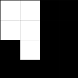
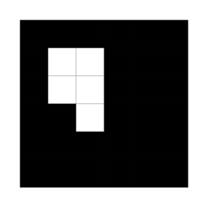
A marker in IV is described by a 4x4 code mask and four corner points. You can easily change the marker code by editing the fields DataSet:World:TrackedObject:Marker:Code:LineX. The marker is made of 4 lines Line1 = 1100 Line2 = 1100 Line3 = 0100 Line4 = 0000 where 0 = black and 1 = white, e.g.

the real marker must have a black square around this and another white square around. It will look like

One way to create and print whose things is to go into word and create a 8x8 table, make the rows and cols the same size and color the cell background with black'n'white.
Code: The visionlib.pm file
<?xml version="1.0" encoding="UTF-8" standalone="no" ?>
<VisionLib2 Version="2.0">

  <ActionPipe category="Action" name="AbstractApplication-AP">
  ... as above
  </ActionPipe>

  <DataSet key="">
    <IntrinsicDataPerspective calibrated='1' camerainfo='unknown vendor and type' key='IntrinsicData' opticsinfo='unknown vendor and type'>
      <Image_Resolution h='480' w='640'/>
      <Normalized_Principal_Point cx='5.0037218855e-001' cy='5.0014036507e-001'/>
      <Normalized_Focal_Length_and_Skew fx='1.6826109287e+000' fy='2.2557202465e+000' s='-5.7349563803e-004'/>
      <Lens_Distortion k1='-1.6826758076e-001' k2='2.5034542035e-001'
                        k3='-1.1740904370e-003' k4='-4.8766380599e-003' k5='0.0000000000e+000'/>
    </IntrinsicDataPerspective>

    <World key="World">
      <TrackedObject key='TrackedObject'>
        <ExtrinsicData calibrated='0' t='0'>
          <R rotation='[1.94006 1.8784 0.5568 ]'/>
          <t translation='[21.0199 -15.4131 126.97 ]'/>
          <Cov covariance='[0.197138  -0.10784  1.11672  0.00494553  0.00655673  -0.00420995  ;
                                    -0.10784  0.0681589  -0.642015  -0.00208031  -0.00403554  0.00560319  ;
                                    1.11672  -0.642015  6.67529  0.0342651  0.0392421  -0.0447934  ;
                                    0.00494553  -0.00208031  0.0342651  0.000935732  0.000448397  6.00177e-005  ;
                                    0.00655673  -0.00403554  0.0392421  0.000448397  0.000896986  -0.000299469  ;
                                    -0.00420995  0.00560319  -0.0447934  6.00177e-005  -0.000299469  0.00270854  ]'/>
        </ExtrinsicData>
        <Marker BitSamples='2' MarkerSamples='6' NBPoints='4' key='Marker1'>
          <Code Line1='1100' Line2='1100' Line3='0100' Line4='0000'/>
          <Points3D nb='4'>
            <HomgPoint3Covd Cov3x3='[0  0  0  ; 0  0  0  ; 0  0  0  ]' w='1' x='0' y='6' z='0'/>
            <HomgPoint3Covd Cov3x3='[0  0  0  ; 0  0  0  ; 0  0  0  ]' w='1' x='6' y='6' z='0'/>
            <HomgPoint3Covd Cov3x3='[0  0  0  ; 0  0  0  ; 0  0  0  ]' w='1' x='6' y='0' z='0'/>
            <HomgPoint3Covd Cov3x3='[0  0  0  ; 0  0  0  ; 0  0  0  ]' w='1' x='0' y='0' z='0'/>
          </Points3D>
        </Marker>
      </TrackedObject>
    </World>

  </DataSet>

</VisionLib2>
You can also change the position of the marker in the world by changing ...Marker:Points3D:HomgPoint3Covd:[xyz] values, make sure the marker stays rectangular and planar. The points describe the outer black border (6x6 field) not the white surrounding, they corrospond to upper left, upper right, lower right, lower left corners of the image.
You can also use multiple markers in one TrackedObject, just duplicate DataSet:World:TrackedObject:Marker and change one of them to reflect its physical position on the object you want to track.
Files: