CAVE cluster
Keywords:
tutorial,
X3D,
engine,
cluster,
stereo,
multi display,
load balancing,
cave
Author(s): Patrick Riess
Date: 2007-12-05
Summary: This tutorial demonstrates how to setup a CAVE environment with three projection walls. It will also take stereo functionality into account which is essential in a CAVE as well as load balancing between cluster PCs.
Preconditions for this tutorial
To get knowledge of multi display configurations and stereo setups, I suggest to work through the other Clustering tutorials and Multiple Views and Stereo. After that you will know everything about a ClusterWindow and Viewareas. Those nodes will be used in this tutorial and extended by a view modifier named ProjectionViewModifier.
Aspects of a CAVE
A CAVE consists of up to six projection walls which are usually aligned orthogonal to each other to build a cubic room or a part of a cubic room. That's the main reason why we have to use ClusterWindow instead of the preconfigured node TiledClusterWindow (see tutorial Multiple display cluster). Each wall shows a different view of the scene, i.e. the camera looks at different directions. So we have to configure each view manually with a ProjectionViewModifier which modifies the camera orientation. Another attribute of a CAVE is it's immersive character, due to stereo projection.

Assumptions
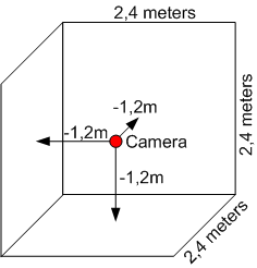
In this tutorial we assume to have a CAVE with 3 walls. A bottom plane, a front plane and one side wall. Each wall has the size of 2.4 x 2.4 meters. We want the camera of our scene to be in the middle of the CAVE. Let's also assume, our scene is modeled in meters, so the side wall is -1.2 to the left of the camera, the bottom plane -1.2 below and the front plane -1.2 to the front (negative z-axis). Each projection should also have a square resolution of 1024 x 1024 pixels, generated by PCs with a standard framebuffer resolution of 1280 x 1024 pixels.

Setting up the views
Now we want to configure a different view for each wall. Therefore a concept exists which allows to define a plane in space with four points. This plane acts as a projection plane for the scene relative to the camera.

The projection plane is configured via the node ProjectionViewModifier, a modifier for the Viewarea node like ShearedStereoViewModifier. It also inherits the fields leftEye, rightEye and eyeSeparation from the stereo modifier.
The projection view modifier for the left wall and the left eye in our CAVE setup will look like this:
Code: ProjectionViewModifier for front wall and left eye
...
modifier [
  DEF mod_front_left ProjectionViewModifier {
    surface [
      -1.2 -1.2 -1.2,
       1.2 -1.2 -1.2,
       1.2  1.2 -1.2,
      -1.2  1.2 -1.2
    ]
    leftEye  TRUE
    rightEye FALSE
    eyeSeparation 0.08
  }
]
...
The surface points have to be counterclockwise, starting with the lower left corner. For the right eye on the same wall you just have to set leftEye to FALSE and rightEye to TRUE.
Respectively the front wall has to be set up like this:
Code: ProjectionViewModifier for left wall and left eye
...
modifier [
  DEF mod_left_left ProjectionViewModifier {
    surface [
      -1.2 -1.2  1.2,
      -1.2 -1.2 -1.2,
      -1.2  1.2 -1.2,
      -1.2  1.2  1.2
    ]
    leftEye  TRUE
    rightEye FALSE
    eyeSeparation 0.08
  }
]
...
And finally for the floor:
Code: ProjectionViewModifier for floor and left eye
...
modifier [
  DEF mod_bottom_left ProjectionViewModifier {
    surface [
      -1.2 -1.2  1.2,
       1.2 -1.2  1.2,
       1.2 -1.2 -1.2,
      -1.2 -1.2 -1.2
    ]
    leftEye  TRUE
    rightEye FALSE
    eyeSeparation 0.08
  }
]
...
Important: Use the same unit (e.g. metres, millimetres) for the projection surfaces like your scene is modeled in. Otherwise you will get interesting field of views.
With stereo configuration we now have 6 different views. Each view should be rendered by one PC. Let's call them front_leftEye, front_rightEye, left_leftEye, left_rightEye, bottom_leftEye and bottom_rightEye. As mentioned in the Assumptions section, each PC has a resolution of 1280 x 1024 pixels. So we will need a window with enough space for each PC (better said framebuffer of PC), which results in a ClusterWindow of a size of 7680 x 1024 pixels. The ClusterWindow configuration now looks like this:
Code: Multi display window for 3-sided stereo CAVE
...
ClusterWindow {
  servers [
    "front_leftEye"
    "front_rightEye"
    "left_leftEye"
    "left_rightEye"
    "bottom_leftEye"
    "bottom_rightEye"
  ]
  size 7680 1024
  fullScreen TRUE
  hServers 6
  vServers 1
  ...
}
...
This configuration results in the following partitioning of the window:

The last missing issue is the setup of view areas on the cluster window, because CAVE walls are square (1024 x 1024) but framebuffers of the PCs are not (1280 x 1024). We will define a square Viewarea per non-square PC region on the cluster window and put one of the above projection view modifiers into each.

Then we will obtain the final configuration:
...
DEF render RenderJob {
  windowGroups [
    WindowGroup {
      windows [
        LocalWindow {
          #This window is just for interaction
          enabled FALSE
        }
        ClusterWindow {
          servers [
            "front_leftEye"
            "front_rightEye"
            "left_leftEye"
            "left_rightEye"
            "bottom_leftEye"
            "bottom_rightEye"
          ]
          size 7680 1024
          fullScreen TRUE
          hServers 6
          vServers 1
          views [
            #Front wall, left eye
            Viewarea {
              lowerLeft  0 0
              upperRight 1023 1023
              modifier [
                DEF mod_front_left ProjectionViewModifier {
                  surface [
                    -1.2 -1.2 -1.2,
                     1.2 -1.2 -1.2,
                     1.2  1.2 -1.2,
                    -1.2  1.2 -1.2
                  ]
                  leftEye  TRUE
                  rightEye FALSE
                  eyeSeparation 0.08
                }
              ]
            }
            #Front wall, right eye
            Viewarea {
              lowerLeft  1280 0
              upperRight 2303 1023
              modifier [
                DEF mod_front_right ProjectionViewModifier {
                  surface [
                    -1.2 -1.2 -1.2,
                     1.2 -1.2 -1.2,
                     1.2  1.2 -1.2,
                    -1.2  1.2 -1.2
                  ]
                  leftEye  FALSE
                  rightEye TRUE
                  eyeSeparation 0.08
                }
              ]
            }
            #Left wall, left eye
            Viewarea {
              lowerLeft  2560 0
              upperRight 3583 1023
              modifier [
                DEF mod_left_left ProjectionViewModifier {
                  surface [
                    -1.2 -1.2  1.2,
                    -1.2 -1.2 -1.2,
                    -1.2  1.2 -1.2,
                    -1.2  1.2  1.2
                  ]
                  leftEye  TRUE
                  rightEye FALSE
                  eyeSeparation 0.08
                }
              ]
            }
            #Left wall, right eye
            Viewarea {
              lowerLeft  3840 0
              upperRight 4863 1023
              modifier [
                DEF mod_left_right ProjectionViewModifier {
                  surface [
                    -1.2 -1.2  1.2,
                    -1.2 -1.2 -1.2,
                    -1.2  1.2 -1.2,
                    -1.2  1.2  1.2
                  ]
                  leftEye  FALSE
                  rightEye TRUE
                  eyeSeparation 0.08
                }
              ]
            }
            #Bottom, left eye
            Viewarea {
              lowerLeft  5120 0
              upperRight 6143 1023
              modifier [
                DEF mod_bottom_left ProjectionViewModifier {
                  surface [
                    -1.2 -1.2  1.2,
                     1.2 -1.2  1.2,
                     1.2 -1.2 -1.2,
                    -1.2 -1.2 -1.2
                  ]
                  leftEye  TRUE
                  rightEye FALSE
                  eyeSeparation 0.08
                }
              ]
            }
            #Bottom, right eye
            Viewarea {
              lowerLeft  6400 0
              upperRight 7423 1023
              modifier [
                DEF mod_bottom_right ProjectionViewModifier {
                  surface [
                    -1.2 -1.2  1.2,
                     1.2 -1.2  1.2,
                     1.2 -1.2 -1.2,
                    -1.2 -1.2 -1.2
                  ]
                  leftEye  FALSE
                  rightEye TRUE
                  eyeSeparation 0.08
                }
              ]
            }
          ]
        }
      ]
    }
  ]
}
...
View areas are set in pixels instead of relative window coordinates for following reasons:
- Readability: Pixel coordinates are much better to associate to a region than something like 0.633205...
- Accuracy: Relative coordinates like 0.633333 are not as accurate than defined pixel coordinates
- Calibration: You don't have to calibrate projectors with pixel accuracy, just calibrate the view areas
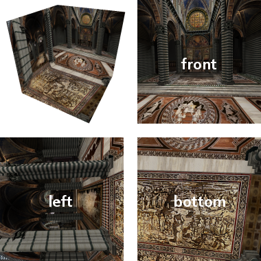
Finally the result are 6 views you need for the CAVE. The image below shows only three views because it doesn't take stereo into account. It shows the Dome of Siena with front, left and bottom views. For a better visualization in the top left corner these views are texturing a virtual 3-sided CAVE.

Load balancing
If you've read the other Clustering tutorials, you will know how to switch load balancing on. Just add these two lines into the ClusterWindow node. The second one is just for debugging purpose to see how load balancing works. Be sure to use Gigabit LAN to obtain an effective balancing.
Code: Activation of load balancing
...
balance TRUE
showBalancing TRUE
...
Head tracking
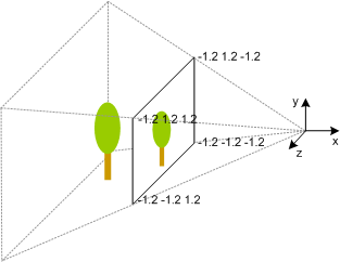
One important issue has not been taken into account yet. As a user is moving around in a CAVE, the eye position is not the same as the camera position which is in the middle due to our setup of the projection planes. So the viewing frustums for each wall are not correct for the users field of view. They have to be adapted to the users position like the image below illustrates.
You see a projection plane with a red and a blue tree. The tree images belong to the red and blue viewing frustums. A users head is represented by coordinate systems which lie at the end of the frustums. When the head moves from blue to red position the accordant frustum is significant to show the correct view on the projection plane.
This additional modification of the camera is also done in the ProjectionViewModifier. A head tracking device is needed which returns a 4 x 4 transformation matrix for position and orientation of a head in a CAVE. The hardware is mostly an infrared or a magnetic device attached to stereo glasses. The device handling is not in scope of this tutorial, but finally if you have a node which produces a transformation matrix from the device, you have to route it to the set_eyeTransform field of all ProjectionViewModifier nodes like this:
Code: Routing of head tracking matrix to ProjectionViewModifiers
...
DEF render RenderJob {
  ...
}

ROUTE headSensor.value_changed TO mod_front_left.set_eyeTransform
ROUTE headSensor.value_changed TO mod_front_right.set_eyeTransform
ROUTE headSensor.value_changed TO mod_left_left.set_eyeTransform
ROUTE headSensor.value_changed TO mod_left_right.set_eyeTransform
ROUTE headSensor.value_changed TO mod_bottom_left.set_eyeTransform
ROUTE headSensor.value_changed TO mod_bottom_right.set_eyeTransform
...