3D Object Tracking
Keywords:
markerless tracking,
structure from motion,
KLT tracking,
Augmented Reality
Author(s): Junming Peng (Jimmy), Martin Buchner, Ajin Joseph, Harald Wuest
Date: 2014-02-12
Summary: This tutorial will give you an overview on how to use Instant Reality's Structure-from-Motion (SfM) module for creating tracking models which can then be used for detecting and tracking a real 3D object without any additional markers.
Introduction
Instant Reality's computer vision framework is capable of tracking real 3D objects without additional markers. In order to achieve this, one must generate a tracking model of the desired object in advance. This can then be used for detecting and tracking the object inside your own application. Instant Vision uses a Structure-from-Motion (SfM) approach for generating a tracking model from a sequence of 2D pictures. This process might be hard to understand for non computer vision developers. Therefore, Instant Vision provides a graphical user interface where developers can just click on a series of buttons to create a 3D object tracking application with ease.
At first, this tutorial will give you a step-by-step guide of the procedures for building a tracking model using Instant Vision. This will be followed by a short description of the code structures. In the end, we will show you some of the results which you can reproduce with the attached paper house template.
Generating a tracking model
Please see images in sequential manner: PreparationStep.png -> FrameHistory1.png -> FrameHistory2.png -> PreparationStep.png.
The creation of a tracking model inside Instant Vision consists of four steps. First of all, one must record a feature point cloud of the object which should be tracked. After this, the features should be transformed into the coordinate system of your virtual objects. Then any unwanted features must be removed. Lastly, the final tracking model and all its components will get generated and saved. We will now describe these steps in greater detail.
1) Recording
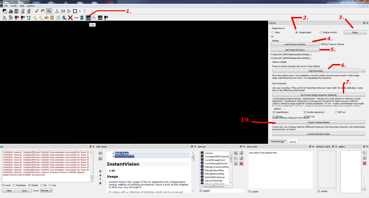
Start Instant Vision. Then reference to Figure 1 and follow the numbers for doing the recording:
- 1. Click on the "SfM" button located at the Activity toolbar. By default, this toolbar might be located at a different spot than seen on the screenshot above. This will update the Activity dock window. On the screenshot, this window is located on the right hand side. If you can’t find this window on your PC, you might have to activate it first by doing a right mouse click on the top toolbar and select "Activity".
- 2. There are three different options for image sources: a. Video: If you select this option, you can use a webcam which is connected to your PC for recording of the tracking model. Please make sure that a suitable video source is selected by clicking on the “Setup” button and then choosing a compatible source and mode. On Windows, the camera source "ds" (directshow) and a mode of “640x480xBI_RGB” usually should work. b. ImageReader: This option will use a previously recorded sequence of pictures as image source. c. HttpServerSink: The HttpServerSink option allows you to record the tracking model using pictures which are streamed from another device. The sending device must send the picture using the HttpClientSource Action. For this tutorial, we assume that you have already recorded an image sequence (e.g. using an iPad, desktop webcam) and we will use the ImageReader image source.
- 3. If you have selected ImageReader as your choice, you may proceed on by clicking the "Setup" button and choosing any image of your recorded sequence (e.g. 0000.jpg) inside the appeared dialog window.
- 4. Load the intrinsic data of the used camera (e.g. iPad2.xml or creative_ultra_int.xml) by clicking on the “Load Camera Intrinsic” button.
- 5. Select a directory for storing the results by clicking on the “Set Project Directory” button.
- 6. Click on the “Start Recording” button to begin the recording of 3D features using the SfM approach (the screenshot above only shows the “Stop Recording” button because the recording has already started). Once you have done so, you should be able to see your images appearing instantly inside the Viewer window. After all images of your image sequence are shown, click on the “Stop Recording” button. If you have selected the “Video” option in step 2 and after you have pressed the “Start Recording” button, you need to move your webcam around the object which you want to track. When you moved and rotated your webcam for a certain amount of time, the Viewer window will freeze for a moment as Instant Vision is trying to determine the 3D position of the first features. During that period of time, please hold your webcam as still as possible. Otherwise the jump to the next image will be too large and Instant Vision can’t track the features from the previous frame to the current frame. As soon as you have captured enough of your object, press the “Stop Recording” button.
- 7. Now, click on the “Re-Process Image Sequence” button. Instant Vision will then clean up the features and tries to re-track all previously recorded frames. During that process, the camera pose will get computed for each frame and will get stored together with the found features inside a structure called “FrameHistory”. Please be patient as this step might take some time. If it takes too long, you might have to try again with a shorter image sequence (around 500 frames should work well).
2) Calibration
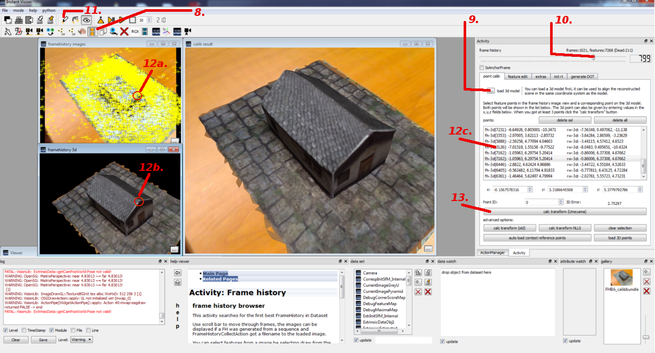
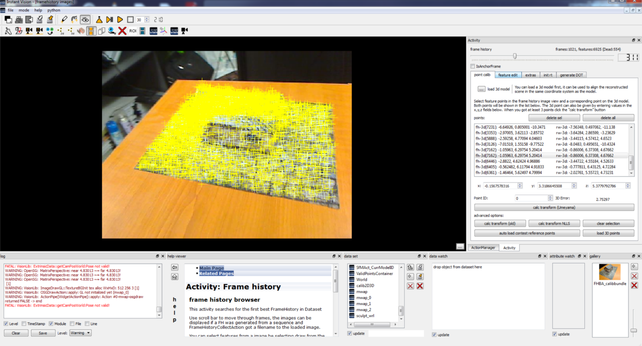
Right now, the computed camera poses and features are in a coordinate system in which the first camera pose sits at the origin and looks along the negative z-axis. This is problematic because the tracking should work in the same coordinate system as your application. Otherwise, it’s very difficult to position the virtual objects which are used to augment the real scene. Therefore, it’s necessary to transform the tracking model into a better coordinate system. Inside Instant Vision, this is done by loading a 3D model and then telling the software which features correspond to which points on the 3D model. Please refer to Figure 2 and the following descriptions for doing this calibration:
- 8. Click on the “FrameHistoryBrowser” button inside the Activity toolbar to start the calibration.
- 9. Load a 3D model of your scene or object. The supported file formats are VRML and partially also OBJ.
- 10. Now, move the slider until you find an image which produces many valid features (bluish) that can also be found easily on the 3D model. Later, you should repeat this step in order to find the corresponding points from different viewer locations.
- 11. Choose the draw tool for selecting corresponding 2D and 3D points.
- 12. a. Mouse click on a valid (bluish) 2D feature point in the “framehistory images” viewer window. b. Mouse click on the corresponding point on the 3D model in the “framehistory 3d” viewer window. c. Mouse click on this space to confirm the selection of your points made at the previous two steps.
- 13. Once you have chosen at least 4 points, you can proceed by clicking on the “calc transform (Umeyama)” button. This will transform the coordinate system of the tracking model so that the previously chosen 3D points are projected onto the 2D points as good as possible. The result can be seen inside the “calib result” viewer window. You might need to move the slider (step 10.) first before the “calib result” viewer window gets updated.
3) Removing unwanted features
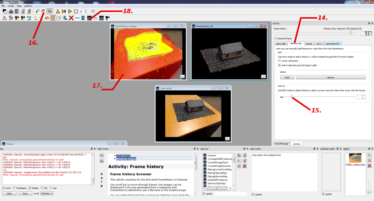
Instant Vision detects features on the whole images but the interesting object usually only covers a part of the images. The remainder of the images belongs to the background which is not constant in the most cases. Therefore, the features from the background would distract the tracking and should be removed. Please reference to Figure 3 and the following steps below on how to erase these unwanted features:
- 14. Select the “feature edit” tab to reveal the options.
- 15. Adjust the size of the eraser which you will later use it to remove the unwanted feature points.
- 16. Select the edit tool to start the erasing process.
- 17. You can remove the unwanted features by clicking with the left mouse button on the “framehistory images” viewer window. On the screenshot above, we have highlighted the unwanted features with red. Please use the frame history slider (step 10.) and repeat the process for all frames until all unwanted features are gone.
- 18. Once you are done, your images should look similar to Figure 4. Now, you can go back to SfM mode for the final processing step.
4) Saving the tracking model
With reference to Figure 1, we would like to conclude and finally create the tracking model for our application:
- 19. Click on the “Create Tracking Models” button to create the tracking configuration. However, the creation process will take a while again so please be patient! During this process, certain post-processing steps will be executed for refining the tracking model. In the end, it will generate the different components of the tracking model. Once everything is completed, you should be able to see “SfMReconTracker.pm” and “SfMReconTracker.x3d” inside your previously chosen project directory. The PM-file is the final tracking configuration. It could be loaded with Instant Vision for testing but it can also be used in an X3D or VRML scene as tracking backend for the Instant Player. The generated X3D file is an example on how to do this.
Code structures
If you open the “SfMReconTracker.pm” file, you will see that it’s quite complex. Therefore, we will briefly explain the most important parts in the following sub-sections.
Code: DOTTrackerAction
			<DOTTrackerAction category='Action' name='ActionPipe'>
				<Keys size='4'>
					<key type='' val='InstantVideosmall' what='image source, in'/>
					<key type='' val='World.Room.DOTDataModel1.DOTContainer' what='container with templates, in'/>
					<key type='' val='DOTPoseOut' what='pose, out'/>
					<key type='' val='IntrinsicsOut' what='intrinsic params of cam, in'/>
				</Keys>
				<ActionConfig ComputeDebugImage='1'/>
			</DOTTrackerAction>
The DOTTrackerAction is used to initialize the tracking by finding the previously recorded object inside the current image (InstantVideosmall). It uses binary image templates (World.Room.DOTDataModel1.DOTContainer) to achieve this. These templates were created and stored together with the respective camera pose during the generation of the tracking model. After a match for one template was found, the corresponding camera pose will get returned (DOTPoseOut). This pose is only a very coarse approximation of the real camera pose. Therefore, we refine this pose using feature based tracking (KLTTrackingAction).
Code: KLTTrackingAction
			<KLTTrackingAction category='Action' enabled='1' name='Action'>
				<Keys size='3'>
					<key val='CurrentImagePyramid' what='input image pyramid, in'/>
					<key val='World.Room.KLTModel1' what='KLT Model, in/out'/>
					<key val='' what='ExtrinsicData, in'/>
				</Keys>
				<ActionConfig MaxBTLevel='5' CalcError='1' CalcProjective='0' CalcProjectiveTrans='0' DontUpdateAffineHelpers='0' EpsBT='0.03' EpsF2F='0.03' ErrorThreshold='30' MaxBTIter='8' MaxIter='8' StoreAnalyserData='0' TrackOnlyNotTrackedFeatures='0'/>
			</KLTTrackingAction>
What the KLTTrackingAction does, is finding correspondences between features found in the previous frames and features found in the current frame. These correspondences can then be used to compute the camera pose. Overall, there are three KLTTrackingActions actively used:
- The first one works together with the DOTTrackerAction. The previously recorded (offline) features (World.Room.KLTModel1) are projected into the image using a coarse camera pose (DOTPoseOut). The KLTTrackingAction then computes the precise initial camera pose.
- The second KLTTrackingAction also uses the previously recorded features but the features are projected using the previous camera pose.
- The third KLTTrackingAction tries to track features which were added during runtime (online).
Code: ShiThomasiCornerDetectAction
			<ShiThomasiCornerDetectAction category='Action' enabled='1' name='ShiThomasiCornerDetect'>
				<Keys size='3'>
					<key val='CurrentImageGreyU' what='input image, in'/>
					<key val='ProjectedPointsContainer' what='existing points, in, optional'/>
					<key val='NewPoints4OnlineRecon' what='detected points, out'/>
				</Keys>
				<ActionConfig CornerCandidatesGridHeight='8' CornerCandidatesGridWidth='8' CornerThreshold='0.02' FeatureDistance='20' MaxNumOfCornersPerGridCell='15' PatchSize='4' ScaleFactor='0.0001' WithDebugOutput='1'/>
			</ShiThomasiCornerDetectAction>
As written before, we are adding new features during runtime. Those features are detected using the ShiThomasiCornerDetectAction. An alternative is the FastFeatureExtractAction. This Action is faster but produces slightly less reliable features than the ShiThomasiCornerDetectAction.
Code: DataSet:World
<World key='World'> <TrackedObject key='Room'> <ExtrinsicData key='ExtrinsicData' calibrated="0"> <R rotation="1 0 0 
"/> <t translation="0 0 0 
"/> <Cov covariance="1 0 0 0 0 0 
0 1.1 0 0 0 0 
0 0 0.9 0 0 0 
0 0 0 0.95 0 0 
0 0 0 0 0 0 
0 0 0 0 0 0 
"/> </ExtrinsicData> <KLTHistoryModel key='KLTModelOR'/> <Inline url='KLTModel.xml'/> <Inline url='DOTDataModel.xml'/> </TrackedObject> </World>
Information about the tracked object is stored inside the World. and load the tracking model which was generated after the “Create Tracking Models” button was clicked. The KLTModel.xml file contains all offline features and the DOTDataModel.xml file stores all binary image templates. If you take a look at these files using a text editor, you can see that they define the KLTModel1 and DOTDataModel1 keys. In case the keys are different, you might have to change them so that they match the keys from the PM-file.
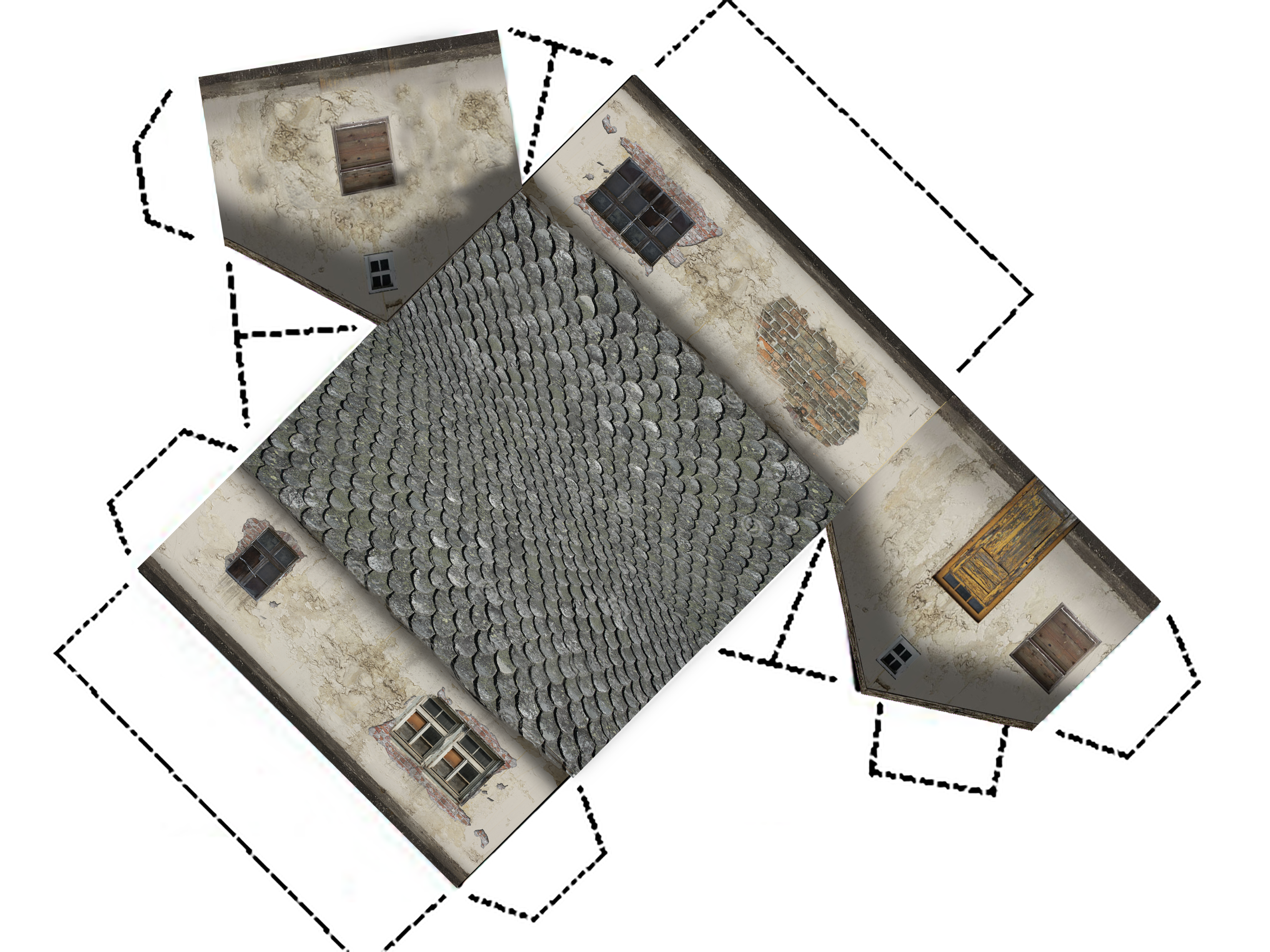
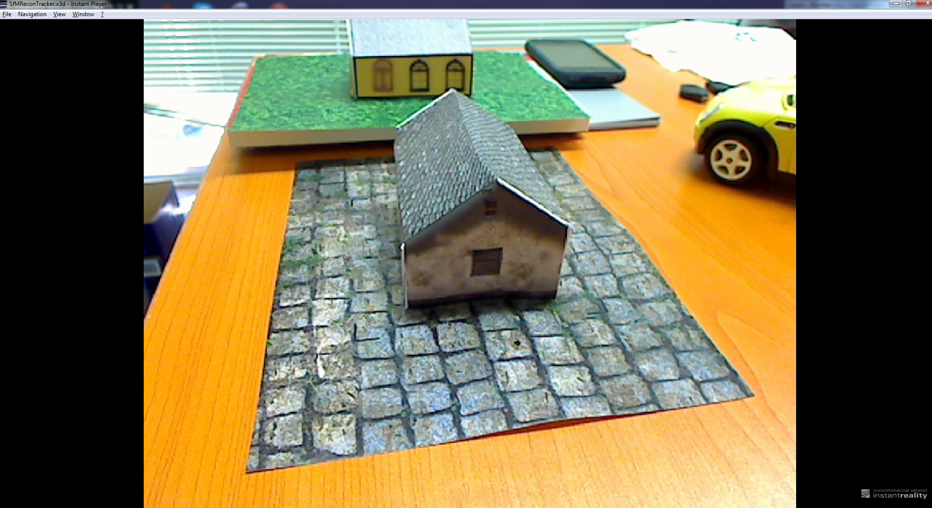
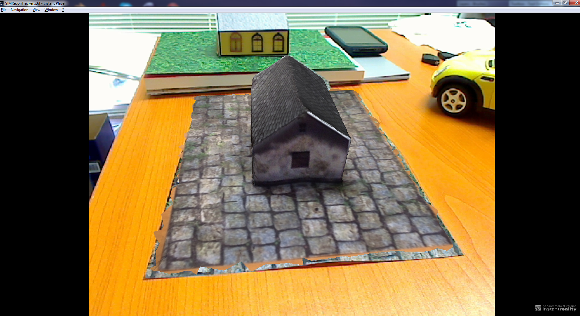
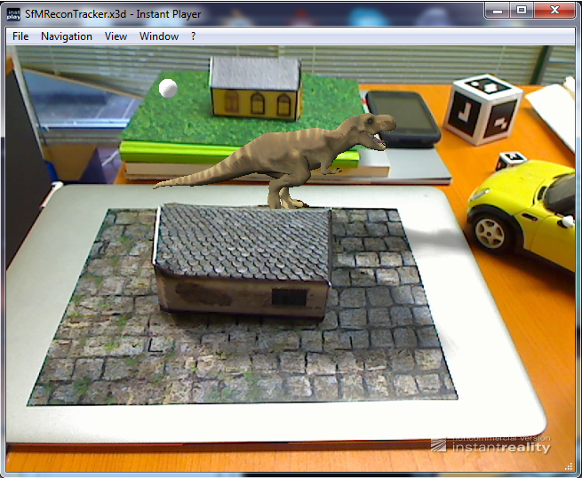
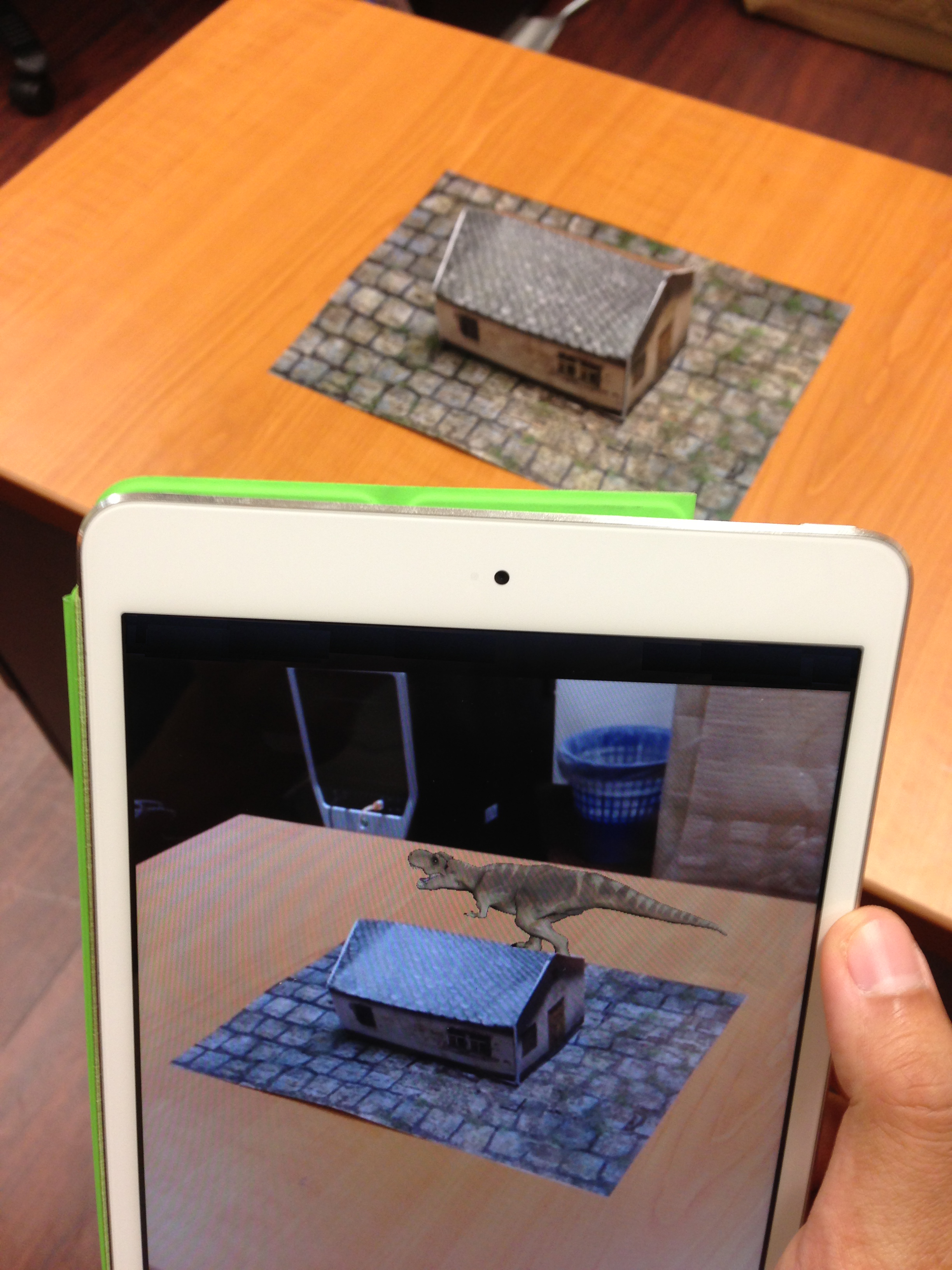
Results After you have gone through this guide, you should be ready to create an object tracking application on your own. We have tagged a few screenshots of the sample application below which showcases the before and after tracking results and not to forget our little paper house template as a reference for the tracking and augmentation to take place ;) . This is just a reference object which you can use to test your tracking and you can definitely replace it with your own real 3D object. We have also showcased the possibility of 3D tracking and augmentation of the paper house using mobile devices (e.g. iPad mini). However, the documentation for the tracking on mobile devices will follow at another time. So stay tuned!
